I decided to export the image and use FabModules to generate the g-code. To do this I exported two images 1. The board. 2. The outline
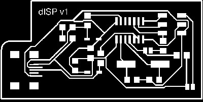

This allowed me to generate two g-code paths; one for the board detail/traces etc; the other to cut the board from the stock sheet. The board path is generated using the 1/64 bit, and the outline with the 1/32
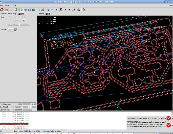
I then had to re-name the files to .ngc to be recognised by the EMC2 CAM software for our mill.
The mill we used is a Sherline 5410. The FR1 was mounted on a wooden backing using double sided tape and the wood was then mounted to the stage. The wooden backing provided a flatter, rigid mounting surface that improved the zeroing of the board and resulted in more uniform cut depth.
X & Y Using the manual contol funtion in EMC2 the mill was moved to the extreme front left and 'home axis' used to zero the axis in this position.
Z The z must be moved manually with the spindle running to ~ 5mm from the board top - turn spindle off. The bit must then be carefully loosened in the chuck and lowered till touching the board surface - re-tighten - move head up - turn on spindle to check concertricity.
Open and Run the board .ngc file - Change the bit to the 1/32 - re-zero the z - run the outline code.
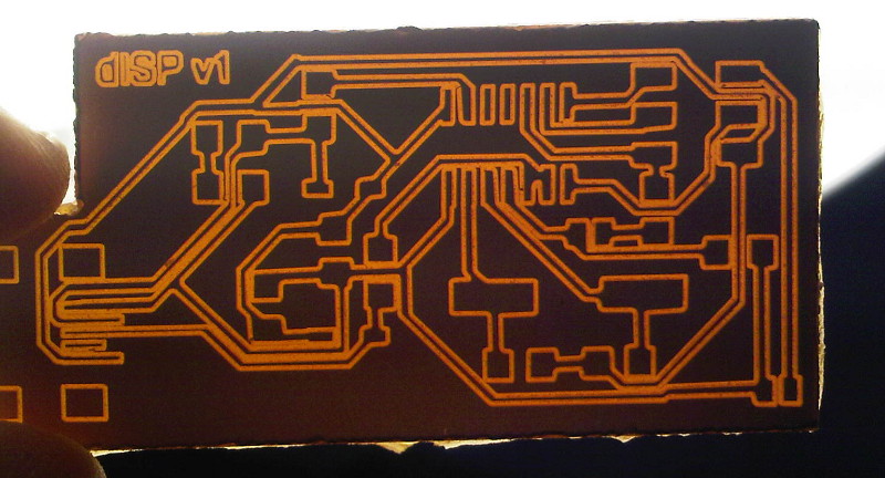
I had two attempts cutting the board with the 1/64 bit. The first with 2 x offset which resulted in very thin traces towards the USB connector, and the second with 1 x offset - better.
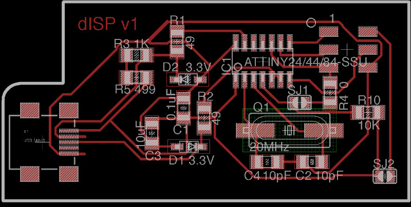
Firstly - Print the board layout and know what each of the components/values are. Having a computer open next to you is ok but harder to tick-off what you have done.
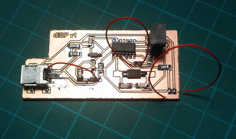
Start with the USB connector then the ATTINY44 as these are the most difficult. Applying the solder to the traces first then placing the components and heating the legs worked best for me. The USB connector can be very difficult, on my first try I burnt one of the traces and had to use a wire jumper to get a connection (red wire from USB). Then work from the centre outwards to make access easier.
Jumpers - SJ1 and SJ2 should be closed. Here i've used a piece of wire to make it easier to remove the connection later. SJ1 should be closed to program the ATTINY - and SJ2 closed to provide power to the target board being programmed.
Check all the connections with the multimetre. Checking for connections to surrounding traces and all adjacent legs.
WORK IN PROGRESS
The Providence page gives excellent step by step instructions. Here.